Monday, August 19, 2013

EIGRP unequal cost load balancing

EIGRP unequal-cost load balancing is one of those topics that we all try to run away from. EIGRP will not perform unequal cost load balancing by default and we have to use the variance command to do so. While working through IE’s vol 2 workbook, I came across a real nice lab that tested unequal cost load balancing. So I decided why not write a brief tutorial that might help others also.
Before we start getting into the configuration, let’s talk about how EIGRP inserts routes in the EIGRP topology table. EIGRP uses two metrics to perform all the calculations:
Advertised Distance (AD): This is the distance that is “advertised” by the upstream neighbor as their cost to the destination.
Feasible Distance (FD): Feasible distance is basically the sum of the Advertised Distance and the distance to the upstream neighbor from the local router.
Successor: Your local router will look through all the advertised paths to a destination and choose the path with the lowest Feasible Distance (FD). This path will have the lowest end-to-end metric and is called the successor. Successor is the best route to the destination.
Feasible Successor: These are paths that can be installed in the routing table if the successor is lost. For a path to be considered a feasible successor, it must satisfy the feasibility condition. A path’s Advertised Distance (AD) mst be lower than the Feasible Distance (FD) of the successor for it to be deemed a feasible successor.
Only routes that are feasible successors can be used for unequal cost load balancing in EIGRP. This is where variance command comes in.
FD of Feasible Successor <= FD of Successor x Variance
This is the only way a feasible successor will be installed in the routing table.
EIGRP Unequal Cost Load Balancing
Let’s look at an example regarding unequal cost load balancing. Our goal is to perform unequal cost loadbalancing at a ratio of 5:1 between the two paths. R1 has two paths to the 164.1.26.0/24 network in the above topology.
Path 1 – R1 > R3 > R2 > VLAN 26
Path 2 – R1 > R2 > VLAN 26
By default, EIGRP will choose the path with the lowest metric. For this topology, the Point to point link between R1-R3 is 1.536 Mbps, frame-relay link between R2-R3 is 1.28 Mbps and the frame-relay link between R1-R2 is 256Kbps. In this scenario, R1 will choose Path 1 to reach VLAN 26. At this point if we configure the variance of 5, then the traffic will be load balanced between the two paths at a ratio of 80:23 as shown in the output below.
RSRack1R1#sh ip route 164.1.26.6       
Routing entry for 164.1.26.0/24
  Known via “eigrp 100″, distance 90, metric 3026432, type internal
  Redistributing via eigrp 100
  Last update from 164.1.12.2 on Serial0/0, 00:00:56 ago
  Routing Descriptor Blocks:
  * 164.1.13.3, from 164.1.13.3, 00:00:56 ago, via Serial0/1
      Route metric is 3026432, traffic share count is 80
      Total delay is 40100 microseconds, minimum bandwidth is 1280 Kbit
      Reliability 255/255, minimum MTU 1500 bytes
      Loading 1/255, Hops 2
    164.1.12.2, from 164.1.12.2, 00:00:56 ago, via Serial0/0
      Route metric is 10514432, traffic share count is 23
      Total delay is 20100 microseconds, minimum bandwidth is 256 Kbit
      Reliability 255/255, minimum MTU 1500 bytes
      Loading 1/255, Hops 1
To achieve a 5:1 ratio, we can modify the metric through R2 to be 5 times the metric through R3. But before we can do that, let’s figure out how the metric is being calculated in the first place. 
Metric = [K1*BW+(K2*BW)/256-Load)+K3*Delay]*[K5/(Reliability+K4)]
As we know, by default K1 and K3 equals 1 while all the other values are ZERO. So we can modify the above equation as follows: 
Metric_R3 = (10^7/BW+Delay/10)*256
Metric_R3 = (10^7/1280+40100/10)*256
Metric_R3 = 3026432 
In order to get the 5:1 ratio, we must increase the metric through R2 to be 5 times that of the metric through R3. This is how we can get the value of the DELAY through R2. 
Metric_R2 = Metric_R3 * 5
(10^7/BW+Delay/10)*256 = (10^7/BW+Delay/10)*256*5
(10^7/256+Delay/10) = (10^7/1280+40100/10)*5
(39062.5+Delay/10 = (7812.5 + 4010) * 5
Delay/10 = 59112.5 – 39062.5
Delay = 20050 * 10
Delay = 200500 
Looking through the routing table, we can see that we already have a delay of 100 microseconds to reach VLAN26. 
RSRack1R2#sh ip eigrp topology 164.1.26.0 255.255.255.0
IP-EIGRP (AS 100): Topology entry for 164.1.26.0/24
  State is Passive, Query origin flag is 1, 1 Successor(s), FD is 28160
  Routing Descriptor Blocks:
  0.0.0.0 (FastEthernet0/0), from Connected, Send flag is 0×0
      Composite metric is (28160/0), Route is Internal
      Vector metric:
        Minimum bandwidth is 100000 Kbit
        Total delay is 100 microseconds
        Reliability is 255/255
        Load is 1/255
        Minimum MTU is 1500
        Hop count is 0
So R1′s local delay to R2 should be (200500 - 100 or 20040 tens of microseconds. Once we configure the delay of 20040 on R1′s Serial interface, we should be able to achieve the 5:1 ratio.


RSRack1R1#sh ip route 164.1.26.6
Routing entry for 164.1.26.0/24
  Known via “eigrp 100″, distance 90, metric 3026432, type internal
  Redistributing via eigrp 100
  Last update from 164.1.12.2 on Serial0/0, 00:00:05 ago
  Routing Descriptor Blocks:
  * 164.1.13.3, from 164.1.13.3, 00:00:05 ago, via Serial0/1
      Route metric is 3026432, traffic share count is 5
      Total delay is 40100 microseconds, minimum bandwidth is 1280 Kbit
      Reliability 255/255, minimum MTU 1500 bytes
      Loading 1/255, Hops 2
    164.1.12.2, from 164.1.12.2, 00:00:05 ago, via Serial0/0
      Route metric is 15132160, traffic share count is 1
      Total delay is 200500 microseconds, minimum bandwidth is 256 Kbit
      Reliability 255/255, minimum MTU 1500 bytes
      Loading 1/255, Hops 1


Using delay is one of the methods of achieving unqual cost loadbalancing. I hope this tutorial has been helpful to you. Don’t forget to leave comments.
- See more at: http://www.ccietalk.com/2008/09/21/eigrp-unequal-cost-load-balancing#sthash.TwSSZckI.dpuf

Single/Dual and Multihomed Connections

Single/Dual and Multihomed Connections


Network engineers will sometimes speak of connections to their ISP(s) in terms of single homed, dual homed, single multihomed, and dual multihomed. Here is a breakdown and clarification of what this terminology means:
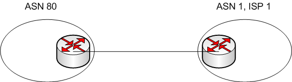
- Single Homed (1 link per ISP, 1 ISP)
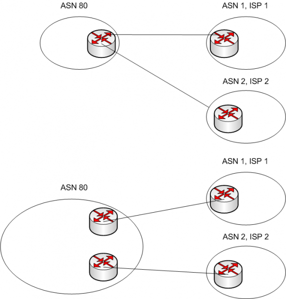
- Dual Homed (2+ links per ISP, 1 ISP)
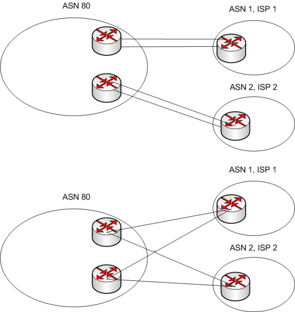
- Single Multihomed (1 link per ISP, 2+ ISPs)
- Dual Multihomed (2+ links per ISP, 2+ ISPs)

Obviously, if you are a datacenter or large enterprise, dual multihomed is definitely costly but the way to go. A dual multihomed setup can help with redundancy, but just as importantly decisions can be made, for instance by BGP (Border Gateway Protocol), on the best path to reach various destinations.. Below are some graphical examples.

Single Homed
Single Homed
Single Homed

Dual Homed
Dual Homed
Dual Homed

Single Multihomed
Single Multihomed
Single Multihomed

Dual Multihomed
Dual Multihomed
Dual Multihomed

Saturday, August 17, 2013

Difference betwen vc mux and llc?

LLC (Logical Link Control) and VC-Mux (Virtual Circuit Multiplexing) are two different methods of data framing or "encapsulation" that are commonly used when transmitting data via a DSL connection.

They are methods of supporting multiple layer 3 protocols (eg IP, Novell IPX or Appletalk) over a single physical circuit, using 1 or more Virtual Circuits, such as the ATM circuit you are using for DSL.

LLC/SNAP embeds a protocol type field into the headers of the layer 2 frame used (the SNAP header), which describes what layer 3 protocol type is being carried within the frame. The device (a router) at the other end looks at this field, and then determines that IP packets should go to the IP forwarding software, IPX packets should go to the IPX forwarding software etc. LLC/SNAP works over a single Virtual Circuit.

VC-Mux on the other hand, uses a separate Virtual Circuit for each different layer 3 protocol.

LLC/SNAP is more efficient when each VC costs money - you only use one for all the Layer 3 protocols your network is using.

VC-Mux is more efficient for transmitting data, as you don't need the protocol type field (and other) overheads.

I'm not exactly sure which type aus DSL uses, VC-Mux would be preferable, as the Internet only runs on layer 3 protocol, that being IP :-)

For more of the details (and probably a better explanation than mine), have a look at rfc2684, formerly rfc1483.

www.faqs.org/rfcs/rfc2684.html

Wednesday, August 14, 2013

勸諫的藝術 |作者:洪大倫

還記得念研究所的時候,就經常帶著大學部的學弟妹,協助他們組成團隊,參加大大小小創業競賽,在這些過程中,我發現對團隊最大的挑戰不是競賽本身,其實是團隊的凝聚力。許多學弟妹有時溝通意見不合,下次開會就不來了,還得指導老師去勸才願意歸隊。

出社會之後,我發現原來這種問題不只是在沒出社會過的學生團隊會出現,在職場上也經常如此。最主要的問題,往往出在同仁之間的溝通產生誤解,進而導致一些爭執;而另一種更大的衝突,有時卻是發生在下屬對主管提出建議時,所引起的一連串政治效應。

前幾天聽朋友Ben說了一個他親身經歷的故事。上週,他剛被老闆欽點升任中區協理,按理說,依我對他的能力了解,高升中區最大的老大一職,應該是時間早晚的問題,但他卻不是這麼說的。

「其實阿,這次升官,公司也走了一個人」朋友說。

「走了誰?」我問。

「就是Jason,那個精明的狠角色」

聽到這個,相當令我訝異,因為根據友人過去的描述,他們兩人差不多時期進公司,只是Jason比他早進入6個月,算是「前輩」,而朋友進入公司時他們兩人還算是有不錯的交情,卻沒想到後來公司似乎有意栽培兩人成為核心幹部,大概因為競爭的關係,Jason開始對朋友越來越疏遠,乃至於在公司暗自較勁了8年。

說起Jsaon,友人其實在過去數年,與我見面時就經常提到他,此人聰明絕頂,年紀雖然大他4歲,但做事相當精巧,像個久年征戰的沙場老將,辦事有效率,對事情的判斷力也很精準,深得主管喜愛,但缺點就是脾氣比較直接,開會時經常獨排眾議,分析情勢頭頭是道,但就是有些得理不饒人。

不過,我這朋友也不是省油的燈,高中大學也是一路名校上去,最後在美國知名學府拿了個碩士學位回來,剛回來就在這家公司任職,表現出色,同樣很受主管青睞。只是他和Jason最大的不同是,他的個性比較隨和,不太喜歡強出頭,雖然對更高的職務有企圖心,但他總是低調的、默默的努力。

「那老闆為什麼選了你?而Jason為什麼後來走了?」我接著問。

「其實,」友人說:「也沒人要他走,是他自己走的,多少有點瑜亮情節吧我想。」

在這閒談中的一個多小時,友人細細談了近期內發生的一件事,就是這件事,產生了決定性的關鍵,讓朋友高升協理,而那位精明幹練的Jason卻選擇在幹了近9年的公司自行離開。

就在約莫三週之前,原先舊的中區協理私下找他和Jason,一起共商下一季度的營運方針與計劃。這次開會比較隱秘慎重,是因為對手公司這次不知道怎麼搞的,集結大量資源準備與他們公司力拼,所以中區主管承受總公司老闆很大壓力,要求務必要想出對策戮力抗敵。

就在協理提出問題之後,Jason立刻自信滿滿的表示:「我認為,公司根本不必在意他們要幹嘛。事實上,對手此時的資源集結,很可能只是空包彈。理由一,他們過去不曾在這產品上有什麼輝煌紀錄,突然說要大力行銷,風險太高,理智一點的公司肯定不會這樣做;理由二,就我所知,他們公司根本就沒有相對應的配套措施,如果有,老早之前某個產品出包的時候就會拿出來,不用等到現在;理由三,他們最近總經理剛換人,我猜想很可能只是為了立威,或者搞一些政治小動作,不是真的要集結資源跟我們拼。」

Jason語畢,協理先是一愣,接著又指著友人說:「Ben,你說說看,你有什麼看法?」

友人回答說,基本上,他大致同意Jason的看法,他也認為這與他過去認識的對手公司印象不同,正所謂新官上任三把火,這的確很可能是對手公司搞的烏賊戰,志不在敵,乃在利用發起商戰,讓權力與資源重新洗牌,將他自己的心腹人馬拉到有利位置。所以建議協理不用過度擔心,按照既定的季度計劃走就可以。

縱然眼前兩位大將都如此分析,但是協理還是不太放心,他依舊認為,萬一沒準備好,而對方真的開始展開攻勢,這可不是鬧著玩的,而且老闆都慎重其事交代了,沒生個什麼特別因應方案的話,好像說不過去,也很難交代。於是協理否決了兩人的分析與建議,強力要求友人與Jason各寫一份計劃書上呈。

既然主管都這麼說了,友人也就不再堅持己見,決定回座位上開始著手寫計劃;反觀Jason就不同了,聽到主管這麼說,他馬上激動的回應:「我真的覺得額外為此準備是浪費時間,協理你一定要跟老闆講,我認為對手這次搞烏賊戰的機率很高,叫他不用擔心這麼多,否則公司因此浪費心血、成本,還要讓底下的同仁弄得人仰馬翻,根本沒有意義。」

協理當下明顯感覺不爽,但也沒有多作表示,只是揮揮手要他們離開會議室,就結束了這場戰情會報。離開會議室後,Jason甚至還憤憤不平的跟友人抱怨,要他怎麼不堅持意見跟協理說,這樣會害大家白忙一場,也要害他浪費時間寫一堆沒用的報告。友人則是沒多說什麼,只是默默聽完之後回到座位上做該做的事。

會議結束後兩週,結果來得相當快,果如Jason所料,對方根本就連產品都還沒準備好,對外放話也只是要干擾他們市場上競爭對手的進程,同時為了這件事,對手公司還升了一位與總經理私交甚篤的同僚,看來還真的被「神算子」Jason給料中!

但這時候真正精彩的好戲才剛剛上演,就在警報解除之後,公司發佈了一項人事命令,將中區協理轉任到總部去服務,而友人Ben居然被拔擢成了新任的中區協理!

這劇情真是急轉直下,連友人Ben都沒料到居然會有這種事發生,但最尷尬而生氣的,大概是Jason,因為他認為自己長年以來許多看法都很正確,然而公司主管老是不採信他,無論他怎麼獨排眾議最後證明他是正確的,似乎主管就是對他有偏見,不願意肯定他的貢獻。於是,就在人事命令發佈後隔幾天,Jason就自己請辭走人了。

聽完這故事,我突然想起以前剛進入職場時,一位前輩對我說的話,他說:「大倫,你雖然很有想法,但年輕氣盛,血氣方剛,如果不懂得收斂,以後吃虧的是你自己。跟主管勸諫的時候,主管聽不聽是他的決定,你不需要堅持己見,縱然事後證明你是對的。」

「為什麼?」我不解地問。

「很簡單的道理,」前輩說:「你只要表明你的看法即可,事後如果證明你是對的,就已經足以證明你的能力,但如果一味堅持恐怕帶來三個不利影響。第一,主管當下可能被你惹毛,對你沒好處;第二,即使主管接納了,結果卻不是你所預料,反而在他心中你就被大大扣分,從此懷疑你的能力有問題;第三,就算結果如你所料,但因為你的意見和他不同而起衝突,更凸顯你的聰明而他像個笨蛋,你說,有哪個主管能容忍自己被下屬當笨蛋看呢?」

當年聽到這個,著實令我心頭大驚,嚇出一身冷汗。

原來,Jason不是沒有能力,而是能力太強,又不懂得收斂,才會讓主管討厭;反而是友人Ben懂得藏拙於巧,冷靜沈潛,才獲得上司的青睞,進而步步高升。

後來我也學到了,給予老闆意見的時候,只要表達一次,確認他有接收到你的資訊就好,不需要過度執著有沒有被接受。「勸諫」固然是一種為人臣的責任,但「不勸諫」也是一種明哲保身的潛規則。懂得在進退之間拿捏分寸,既尊重主管,又能讓自己避開無謂的紛爭,才是上上之策。

只懂「進」,不懂「退」,充其量只能當個普通的職員;只有同時懂得「進」「退」之妙者,方能成就大業。這是每個人都需要學習的職場技巧,更是每個創業團隊彼此溝通時,要小心注意的處世之道。

Thursday, August 8, 2013

DLSw: Data-Link Switching protocol

DLSw: Data-Link Switching protocol
Data-link switching (DLSw) provides a forward mechanism of transporting IBM Systems Network Architecture (SNA) and network basic input/output system (NetBIOS) traffic over an IP network. DLSw does not provide full routing, but instead provides switching at the SNA Data Link layer (i.e., layer 2 in the SNA architecture) and encapsulation in TCP/IP for transport over the Internet.
DLSw, originally a proprietary IBM protocol, was adopted by IETF as a standard. DSLw version 1 (DSLw v1) defines three primary functions:
  • The Switch-to-Switch Protocol (SSP) is the protocol maintained between two DLSw nodes or routers.
  • The termination of SNA data-link control (DLC) connections helps to reduce the likelihood of link layer timeouts across WANs.
  • The local mapping of DLC connections to a DLSw circuit.
DLSw version 2 (DLSw v2) was introduced in 1997 in IETF, which provides the following enhancements to the version 1:
  • IP multicast
  • UDP unicast responses to DLSw broadcasts
  • Enhanced peer-on-demand routing
  • Expedited TCP connections

Each of these features enables DLSw as a scalable technology over WANs. In DLSw Version 1, transactions occur with TCP. As a result, many operations in a DLSw environment consumed circuits between peers. For example, a multicast required multiple TCP connections from the source to each peer. With DLSw Version 2, multicast is distributed using unreliable transport following traditional multicast methods.
Cisco supports a third version of DLSw called DLSw+. DLSw+ predates DLSw Version 2 and provides even further enhancements to basic DLSw.

Protocol Structure - DLSw: Data-Link Switching protocol Header 

8162432 bit
Version numberHeader LengthMessage Length
Remote data link correlator
Remote DLC port ID
Reserved FieldMessage typeFlow control byte
  • Version number - Set to 0x31 (ASCII 1) indicating a decimal value of 49. This is used to indicate DLSw version 1.
  • Header length - Set to 0x48 for control messages and 0x10 for information and Independent Flow Control messages.
  • Message length - Specifies the number of bytes within the data field following the header.
  • Remote data link correlator - Works in tandem with the remote DLC port ID to form a 64-bit circuit ID that identifies the DLC circuit within a single DLSw node. The circuit ID is unique in a single DLSw node and is assigned locally. An end-to-end circuit is identified by a pair of circuit IDs that, along with the data-link IDs, uniquely identifies a single end-to-end circuit.
  • Remote DLC port ID - Works in tandem with the remote data-link correlator to form a 64-bit circuit ID that identifies the DLC circuit within a single DLSw node. The contents of the DLC and DLC Port ID have local significance only. The values received from a partner DLSw must not be interpreted by the DLSw that receives them and should be echoed "as is" to a partner DLSw in subsequent messages.
  • Message type - Indicates a specific DLSw message type. The value is specified in two different fields (offset 14 and 23 decimal) of the control message header. Only the first field is used when parsing a received SSP message. The second field is ignored by new implementations on reception, but it is retained for backward compatibility.
  • Flow control byte - Carries the flow-control indicator, flow-control acknowledgment, and flow-control operator bits.

Related Protocols
SDLC , NetBIOS , TCP , SMP , Ethernet , Token Ring , SNA

Sponsor Source
Data-Link Switching (DSLw) was originated by IBM and adopted as a standard by IETF.

Reference
http://www.javvin.com/protocol/rfc1795.pdf : Data Link Switching: Switch-to-Switch Protocol AIW DLSw RIG: DLSw Closed Pages, DLSw Standard Version 1.0
http://www.javvin.com/protocol/rfc2166.pdf : DLSw v2.0 Enhancements 
Related Posts Plugin for WordPress, Blogger...